Welcome to the JeepSpecs.com in-depth page on the WJ Generation Jeep Grand Cherokee fuse diagram. We have organized as much information as we could find into a helpful table below. Is something incorrect or missing? Please get in touch with us and we’ll fix it!
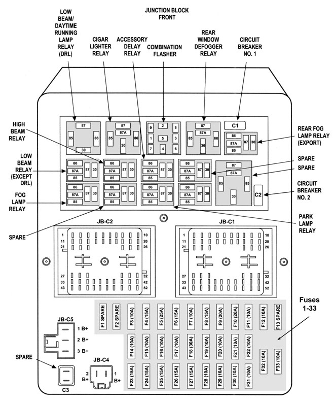
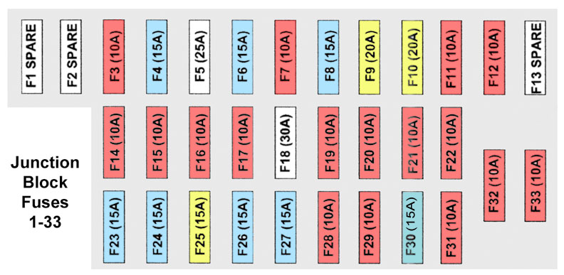
WJ Junction Block (under dash, left of steering wheel).
Grand Cherokee fuses
1999-2004

| Cavity | Fuse | Color | Description |
| F1 | — | — | Spare |
| F2 | — | — | Spare |
| F3 | 10 Amp | Red | Headlight high beam left |
| F4 | 15 Amp | Lt. Blue | Flasher, hazard switch (see Junction Block diagram above for location of turn signal Flasher relay – Mopar p/n 4686094)(Repair tip: WJ flasher repair)
Note: On some or all WJ models, this fuse is also used for the ashtray light and the shifter assembly light. |
| F5 | 25 Amp | Natural | Radio amplifier |
| F6 | 15 Amp | Lt. Blue | Park lamps |
| F7 | 10 Amp | Red | Interior lights |
| F8 | 15 Amp | Lt. Blue | Overhead console, rear wiper, IP lights, rear flipper glass solenoid, power locks |
| F9 | 20 Amp | Yellow | Power outlets |
| F10 | 20 Amp | Yellow | Adjustable pedals (2002-2004 only) |
| F11 | 10 Amp | Red | Rear window defrost indicator |
| F12 | 10 Amp | Red | Auto shutdown relay / “Fuel” |
| F13 | — | — | Spare |
| F14 | 10 Amp | Red | Headlight low, left |
| F15 | 10 Amp | Red | Headlight low, right |
| F16 | 10 Amp | Red | Headlight high, right |
| F17 | 10 Amp | Red | Instrument cluster, diagnostic connector |
| F18 | 30 Amp | ? | Trailer tow |
| F19 | 10 Amp | Red | Anti-lock brakes |
| F20 | 10 Amp | Red | Ignition Run / Heated seats / A/C Heater control / Flasher – Left and Right turn signal switch sense |
| F21 | 10 Amp | Red | Ignition Run / Start – PDC (Power Distribution Center) |
| F22 | 10 Amp | Red | Ignition Run / Start |
| F23 | 15 Amp | Lt. Blue | Brake switch |
| F24 | 15 Amp | Lt. Blue | Foglamps |
| F25 | 20 Amp | Yellow | Accessory delay relay (sunroof) |
| F26 | 15 Amp | Lt. Blue | Cigar |
| F27 | 15 Amp | Lt. Blue | Rear fog (export) |
| F28 | 10 Amp | Red | Body Control Module, Acc/Run |
| F29 | 10 Amp | Red | Rear wiper switch. Washer motors |
| F30 | 15 Amp | Lt. Blue | Radio |
| F31 | 10 Amp | Red | Ignition Start |
| F32 | 10 Amp | Red | Ignition Run / Start – Airbag |
| F33 | 10 Amp | Red | Ignition Run / Only – Airbag |
| C1 | 20 Amp | Yellow | Wiper (Circuit Breaker) |
| C2 | 20 Amp | Yellow | Seats (Circuit Breaker) |
| C3 | — | — | Spare |
Junction Block pinouts
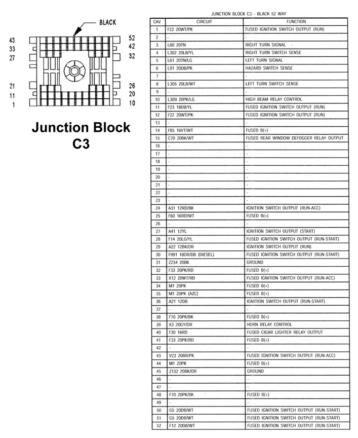
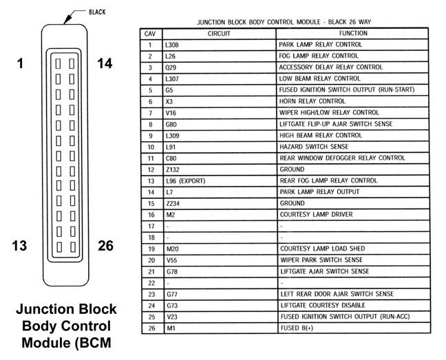
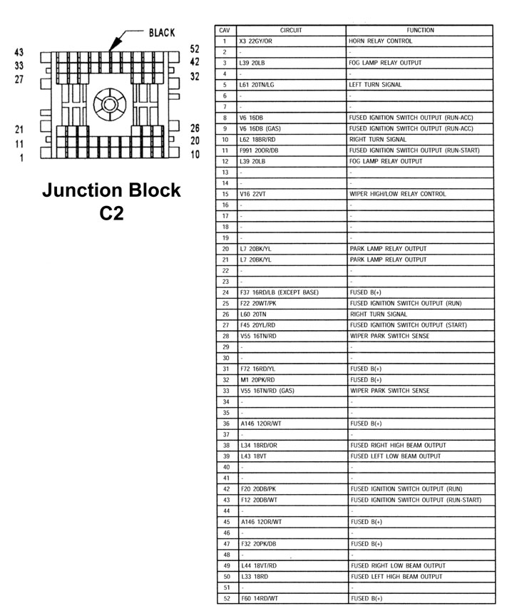
| Junction Block C-2 | Body Control Module | Junction Block C-3 |
|---|
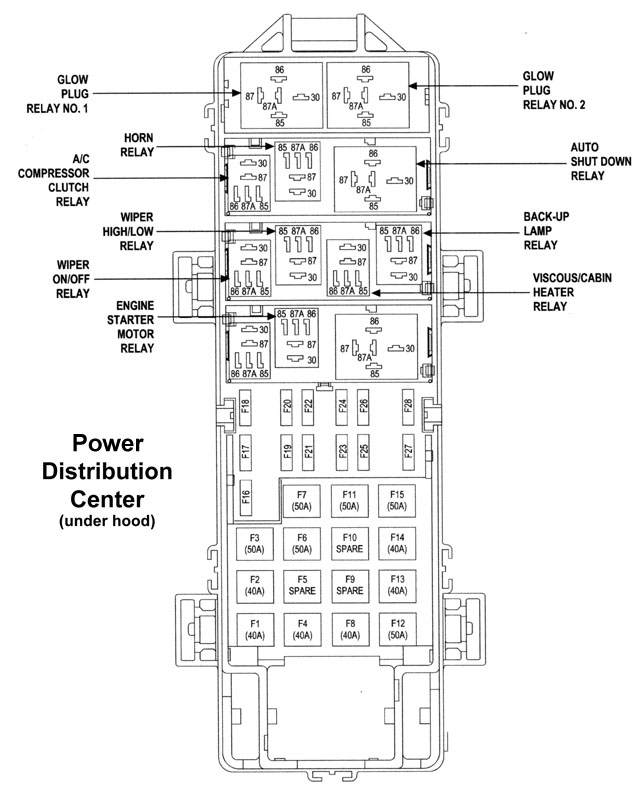
PDC (Power Distribution Center, under hood)
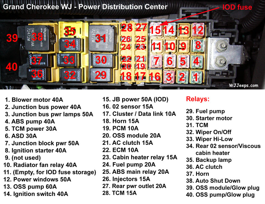
The IOD connector can be used by the vehicle owner as a convenient means of reducing battery depletion when a vehicle is to be stored for periods not to exceed about twenty days (short-term storage). Simply disconnect the IOD connector from the JB receptacle slot # 15 and place it in slot # 11 (see diagram above). However, it must be remembered that disconnecting the IOD connector will not eliminate IOD, but only reduce this normal condition. When a vehicle will not be used for more than twenty days, but less than thirty days, remove the IOD fuse from the Power Distribution Center (PDC). If a vehicle will be stored for more than about thirty days, the battery negative cable should be disconnected to eliminate normal IOD; and, the battery should be tested and recharged at regular intervals during the vehicle storage period to prevent the battery from becoming discharged or damaged. Refer to Ignition-Off Draw Fuse and Battery in the index in this service manual for the location of additional service information covering the ignition-off draw fuse and the battery.
WJ flasher repair tip
The flasher is located in the Junction Block (under the dash, left of steering wheel. See diagram at very top of this page). The following repair tip was provided by “tntguy”:
Look at the end of the flasher relay with the prongs sticking out. There will be 2 plastic tabs holding it together. Break or bend these back. Pull out the insides. On one side will be all the components. On the other side will be solder joints. Get a magnifying glass and inspect these joints. One or two will probably have stress cracks. Just dab a little flux on this joint and heat it with a soldering iron until it melts back together. You may need to add just a little solder. Be sure to get the pins hot and not just the solder. They need a lot of heat. Slide the relay back into its cover, dab a little super glue or tape it back together, and you’re ready to go.